Hardware Interface
As it was mentioned in the project presentation chapter (Project Structure), Libre-Printer relies on an interface that receives the print data coming from a computer.
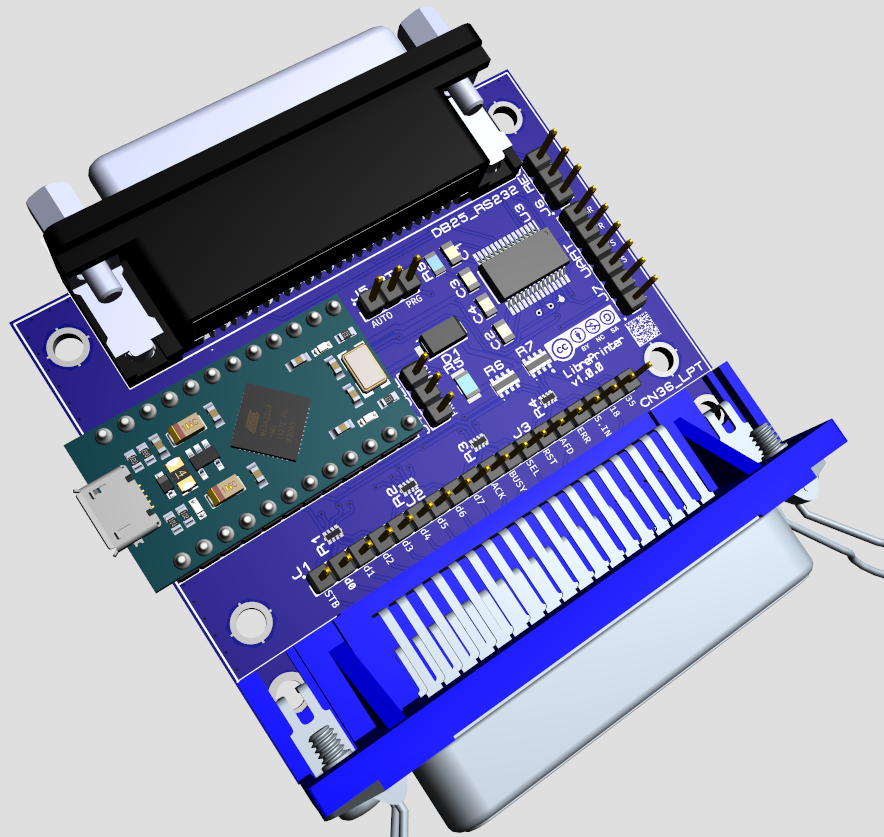
Libre-Printer interface (version 1.0.0)
LED indications
The microcontroller of the interface is currently an Arduino ProMicro whose diagram below:
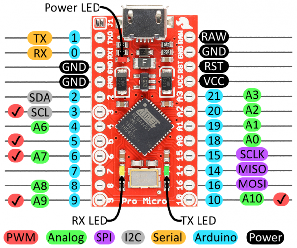
Arduino ProMicro pinout
Here’s how the LEDs of the Arduino behave:
Power LED (green) |
Lit as soon as the interface is powered on |
TX LED only (red) |
Interface waiting for configuration |
RX LED flashes at a rate of 1/second (red) |
Interface ready to receive print data |
RX LED flashes briefly + TX LED continuously |
Interface receiving data and relaying it |
TX LED + RX LED during ~7seconds |
Interface in boot mode after a manual reset |
Datasheet & list of components
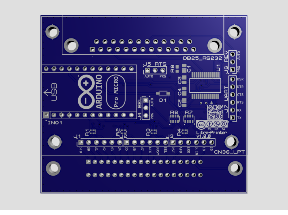
Libre-Printer Printed Circuit Board design without components (version 1.0.0)
The files required to build the project’s electronic board are available on the Git repository in the hardware folder.
TBA
Component roles & optional components
In the vast majority of cases, the interface can be used as is without requiring modifications or additional components. However, the circuit offers customization options to accommodate implementations that deviate from what was considered standard at the time. Obviously, if only one of the two interfaces (serial or parallel) is needed, the components related to the unused interface are dispensable.
It is important to understand that the IEEE 1284 standard for bidirectional parallel communications between computers and peripherals was established in 1994. However, the parallel port and its connector, released by Centronics, date back to the 1970s. Twenty years have passed during which the interfaces and their implementations evolved according to the manufacturers’ desiderata for their models.
In parallel (no pun intended), the serial interface never benefited from standardization, even as late as IEEE 1284. The DB25 interfaces found on the IBM PC are RS232 serial interfaces, which many mistakenly associate with what was known as a parallel port until the 2000s.
Thus, most DB25 cables are RS232 serial cables, used before the 9-pin DE-9 connector (commonly called DB9) replaced them.
The DB25 connector is indeed a swampland of non-standard norms; the straight 25-wire cable is quite rare. Additionally, all combinations of pins and logical states for hardware flow control have been used. For example, the DTR/DSR, RTS/CTS, DTR+REV/DSR, DTR+REV/DSR+DCD pairs. For example, while the DTR and REV pins are supposed to follow each other, if it turns out that some machines use different states for them (high or low state to signal available material), then the number of possible combinations becomes very large.
Component part no.
Optional
Parallel
Serial
INO1
x
x
J1
x
x
J2
x
x
J3
x
x
J4
x
x
R1
x*
x
R2
x*
x
R3
x*
x
R4
x*
x
R6
x*
x
R7
x*
x
D1
x*
x
R8
x
x
J5
x
x
J6
x
x
J7
x
x
C1
x
C2
x
C3
x
C4
x
U1
x
*: Normal parallel operation not guaranteed, see below.
Parallel Interface
The parallel interface is present via the CN36_LPT connector. Connectors J1, J2, and J3 are present for debugging or measurement purposes.
Standard Pins:
Protection resistors R1, R2, R3, R4 and pullup resistors R6, R7, D1 can be omitted; In this case, the first ones (R1-R4) must be bridged to allow the signals to pass. While it’s allowed for test cases, the interface should work™ most of the time but it’s far from guaranteed…
Unused Pins:
Some pins are not used or optional; thus Autofeed, Reset, SelectIn
are not currently used although routed, protected, and kept high by
pull-up resistors R6 & R7.
Non-standard Pins:
Non-standard pins, normally unassigned, can be kept high because some equipments require it (cables or devices). For example, the Commodore C64 seems to require a 5V voltage on pin 18.
Pin 35 may may also require a high state for some equipment. The pad near pin 4 of resistor R7 should be connected for this purpose.
Options:
Jumper 4 - Signal Select (output)
The
Selectpin signals to the computer that the printer is available, the voltage level required for this signal is 5V.Selectcan be controlled by the firmware; in this case, a connection between pins 2 and 3 of jumper J4 should be made (this is the default case).Otherwise, the interface should signal itself as a constantly connected printer. A bridge between pins 1 and 2 of jumper J4 should be made and the pull-up resistor R6 should be present.
Serial Interface
The serial interface is present via the DB25 RS232 connector. The J7 connector is present for debugging purposes for the TTL levels (≤ 5V) of the RS232 interface (so-called UART interface).
Options:
Jumper 5 - Signal RTS (output)
Most serial printers require this pin to be high as soon as the printer is connected. As with the
Selectpin for the parallel interface, the state of this pin is configurable: Either from the firmware for hardware flow control (by connecting pins 2 and 3 as is the default), or fixed to high permanently via a pull-up resistor R8 (by connecting pins 1 and 2).Jumper 6 - Signal REV (output)
The DTR signal indicates that the printer is ready to receive data, this signal is normally connected to the REV pin (non-standard in a DB25 RS232 cable). Most of the time, and normally, this signal is high logic; however, some equipments operate in low logic. Hence, the REV and DTR pins can adopt different logical states.
Pins 2 and 3 of jumper 6 are connected by default for a REV pin that follows the logic of the DTR pin. Otherwise, REV should be controlled independently; a connection between pins 1 and 2 should be made at the expense of the default connection between 2 and 3.
License
See the chapter Licenses.